Five-axis joint bracket for a robot arm
Stiffness without mass — a 5-axis bracket with undercuts, 18% lighter and 0.021 mm position error.
What made this part difficult
The bracket sat between a harmonic drive and the arm structure, with bearing bores on two perpendicular faces, an undercut for cable routing and a mass target the previous design had missed by 15%. Every extra gram at that joint showed up as compliance at the tool centre point.
Three changes that made it repeatable
- 01
Re-cut the pocket geometry with the customer’s engineer to remove material from low-stress zones while keeping a 4 mm wall around both bearing bores.
- 02
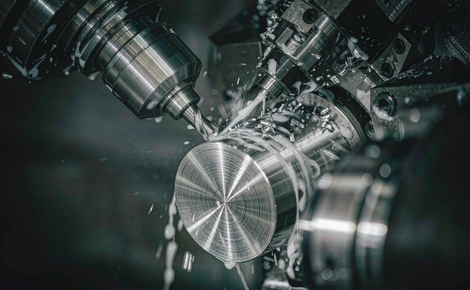
Machined the part in one 5-axis setup from 7075 plate, so the two bore axes stayed in the same datum frame instead of being re-fixtured.
- 03
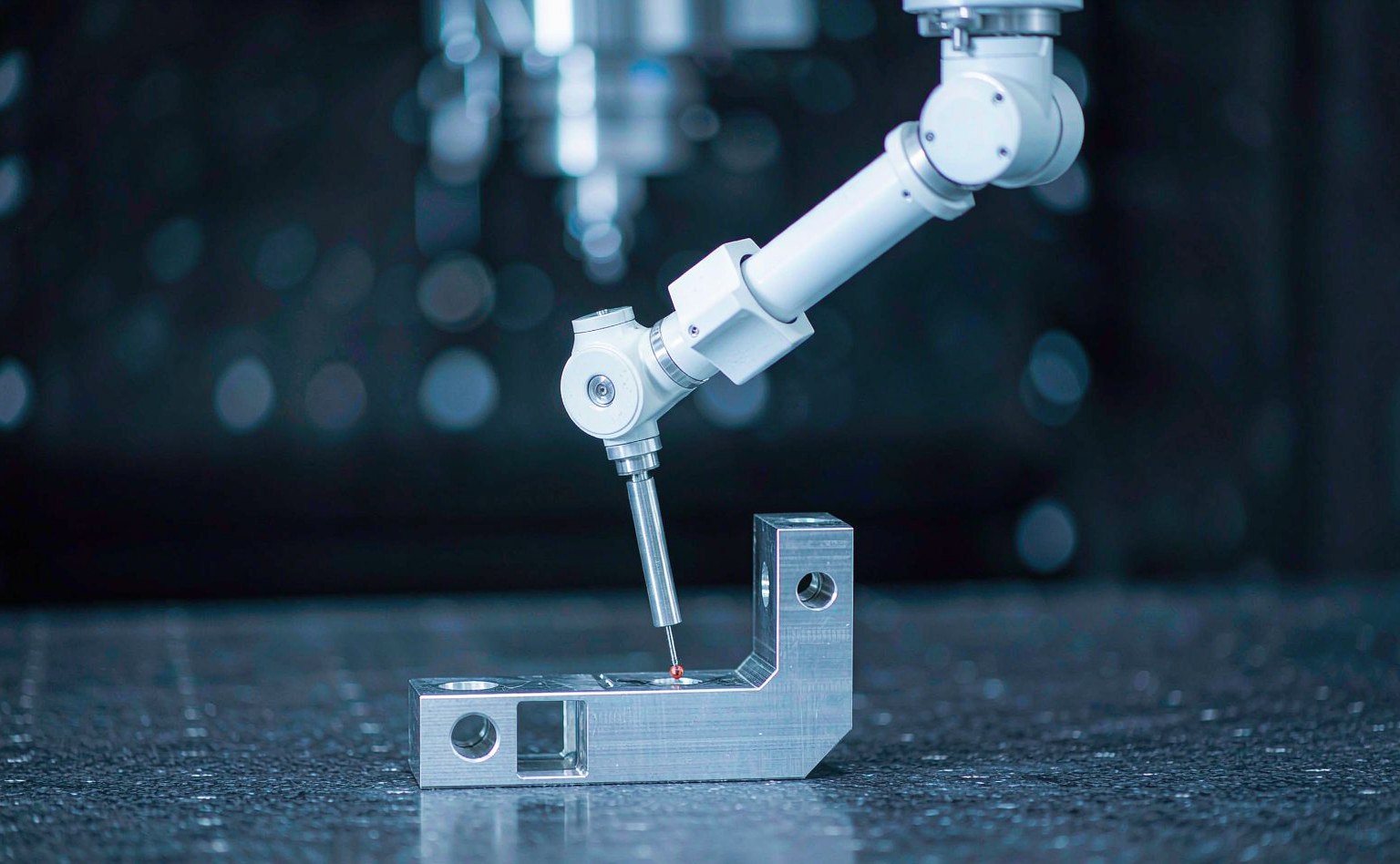
Stress-relieved the blank before finishing, then measured both bores and the mounting face on the CMM at 20 °C.
Measured, not claimed
mass against the previous bracket, with the same bearing bore sizes.
position error on the two perpendicular bores, against a 0.03 mm callout.
from approved model to inspected part, including stress relief.
Measured on a calibrated CMM at 20 °C. The inspection report shipped with the parts.
Project gallery